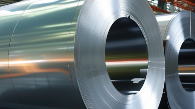
Choosing the right Silicon Steel Sheet starts with the job it must perform. A transformer core and a motor stator face different magnetic demands. One may prioritize low core loss at a steady frequency. The other may need reliable performance as its magnetic field repeatedly changes. The grade name alone cannot tell the whole story.
In this guide, fictional electrical-steel specialist Alex Morgan offers a practical rule: “Choose the steel for the magnetic circuit, not the catalog headline.” This is an original illustrative quote, not a sourced statement. Compare grain-oriented and non-oriented grades against the equipment’s design. Check core-loss data at the intended frequency and flux density. Then confirm thickness, coating, and stacking factor. A thin sheet can help limit eddy-current losses, but only if its properties suit the application. At the workbench, clean edges and consistent laminations matter, too.
Selection is rarely perfect on paper. A datasheet may not reflect every operating condition, and a lower quoted price can hide added processing needs. Ask suppliers for test conditions, tolerances, and traceable product data. If possible, validate the chosen grade in a representative core before committing to production. Small differences can show up as extra heat, a faint hum, or disappointing efficiency. This article explains how to weigh those details, question convenient assumptions, and choose with evidence rather than guesswork.

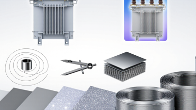
Choosing silicon steel starts with the job the core must perform. A transformer operating at steady mains frequency has different needs from a motor exposed to changing magnetic fields. Grain-oriented sheet is commonly considered for transformer cores, where flux follows a preferred direction. Non-oriented sheet suits many rotating machines, where flux changes direction around the core. Match the material to the magnetic path.
Then check the operating conditions. Record the frequency, expected flux density, temperature, and duty cycle. Higher frequency can make core losses more significant, while elevated temperatures may affect insulation and performance. Look at the manufacturer’s loss data at conditions close to your design—not just one headline value. A neat catalog figure can mislead. Real waveforms are not always neat.
Manufacturing matters, too. Thin sheets can help reduce eddy-current losses, but they may require more careful handling and stacking. Cutting, punching, or bending can strain the material and change its magnetic behavior. Check coating compatibility with the joining method, and allow for the space taken by insulation between layers. If the application is still uncertain, test a small core under realistic load and temperature. I have seen designs look sound on paper, then reveal losses after assembly. That possibility deserves attention.
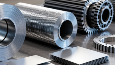
Choosing silicon steel starts with the magnetic path, not just the grade label. Grain-oriented steel suits transformer cores, where flux follows the rolling direction. Non-oriented steel suits motor cores, where flux repeatedly changes direction. Check core loss, magnetic induction, thickness, and stacking factor against your design frequency and operating flux.
IEC 60404-8-4 lists M400-50A non-oriented steel with a maximum specific total loss of 4.00 W/kg at 1.5 T and 50 Hz. For comparison, IEC 60404-8-7 lists M120-27P grain-oriented steel at 1.20 W/kg at 1.7 T and 50 Hz. These figures come from different test inductions, so they are not a direct performance ranking. Read the test conditions carefully. A lower loss value can look attractive, but cut edges, stress, and poor stacking may raise real core losses. That detail is easy to overlook. I would also compare supplier test certificates with the applicable IEC method, then validate a small assembled core. Grade data narrows the choice; it does not replace testing.
| Grade or Material Type | Typical Thickness | Maximum Specific Total Loss | Magnetic Test Condition | Magnetic Characteristics | Common Applications | Selection Guidance |
|---|---|---|---|---|---|---|
| M270-35A Non-oriented electrical steel |
0.35 mm | 2.70 W/kg | 1.5 T, 50 Hz | Low core loss; magnetic properties are broadly similar in different in-plane directions. | Efficient motors, generators, and small transformers | A suitable starting point when reducing core loss matters and the equipment uses alternating magnetic flux in multiple directions. |
| M350-50A Non-oriented electrical steel |
0.50 mm | 3.50 W/kg | 1.5 T, 50 Hz | Moderate core-loss level with general-purpose non-oriented magnetic behavior. | General-purpose motors, pumps, and appliances | Consider for cost-conscious designs where the loss target is less demanding than for higher-efficiency equipment. |
| M400-50A Non-oriented electrical steel |
0.50 mm | 4.00 W/kg | 1.5 T, 50 Hz | Higher specified loss than M350-50A; properties remain non-oriented. | Standard motors and magnetic components | Compare its lower material cost, where available, against increased operating core loss. |
| M470-50A Non-oriented electrical steel |
0.50 mm | 4.70 W/kg | 1.5 T, 50 Hz | Higher loss class among these examples; suitable where the magnetic-loss requirement is more relaxed. | Cost-sensitive motors and general magnetic circuits | Use only after checking that the resulting efficiency and temperature rise meet the design requirements. |
| Conventional grain-oriented (GO) Grade depends on the applicable standard |
Commonly about 0.23–0.30 mm | Often roughly 0.8–1.2 W/kg for representative grades | Typically compared at 1.7 T, 50 Hz; confirm the grade’s specified test point | Very strong magnetic performance along the rolling direction; properties are direction-dependent. | Power and distribution transformer cores | Choose when the core’s main flux path can follow the rolling direction. The loss range is indicative, not a grade guarantee. |
| High-permeability grain-oriented (Hi-B GO) Grade depends on the applicable standard |
Commonly about 0.20–0.27 mm | Often roughly 0.7–1.0 W/kg for representative grades | Typically compared at 1.7 T, 50 Hz; confirm the grade’s specified test point | Enhanced permeability and low loss along the rolling direction; strongly anisotropic. | High-efficiency transformer cores | Consider for transformer designs prioritizing low no-load loss; account for processing, joint design, and direction of flux. |
| How to read the non-oriented grade codes: In these IEC-style designations, the number after “M” indicates the maximum specific total loss in hundredths of a watt per kilogram at the stated test condition; the next number indicates nominal thickness in hundredths of a millimetre. “A” identifies non-oriented electrical steel. Values shown for these listed grades are maximum loss values, not typical measured results. Always check the applicable standard, frequency, induction, thickness, coating, and supplier test certificate before comparing materials. | ||||||
Sheet thickness affects both magnetic performance and core construction. Thinner laminations generally help limit eddy-current losses, especially as operating frequency rises. They can also cost more and require careful handling. A thicker sheet may suit a lower-frequency design where stiffness and simpler assembly matter. There is no universal best thickness. Compare options using the intended frequency, flux density, core shape, and thermal limits.
Coating matters just as much. Its insulation separates adjacent laminations and helps reduce circulating currents. Check that the coating’s temperature rating and compatibility suit the manufacturing process and operating conditions. Cutting can damage insulation at edges, while burrs may create unwanted electrical contact. Inspect sample stacks after cutting and assembly. A neat spreadsheet still cannot capture every production detail, and I would treat early estimates as provisional.
Tips: Start with the equipment’s actual frequency and temperature range. Ask for measured loss data at relevant conditions, not just a material grade. Compare coating coverage, stacking factor, and edge quality on a small trial core. Then review the results against your design targets. Even a minor coating defect can matter.
Choosing silicon steel sheet means checking the factory process, not just the grade on a datasheet. Confirm thickness, coating, width, and punching or laser-cutting needs before requesting quotations. Grain-oriented steel suits transformer cores with a defined magnetic path; non-oriented steel is commonly used in rotating machines. The International Energy Agency’s 2023 report, Electricity Grids and Secure Energy Transitions, says annual grid investment must rise from about $300 billion to more than $600 billion by 2030. That points to stronger demand for grid equipment, but it does not guarantee local sheet availability. Ask suppliers about stock, minimum order quantities, mill certificates, and realistic delivery windows. Lead times matter.
Cost should be compared per finished core, not per kilogram alone. Cutting burrs, coating damage, scrap, and annealing requirements can change both yield and magnetic performance. The U.S. Department of Energy’s 2021 U.S. Industrial and Commercial Motor System Market Assessment reports that motor-driven systems account for roughly 54% of U.S. manufacturing electricity use, making efficiency losses worth checking carefully. Request core-loss data at the intended frequency and induction, then verify it against the actual design. A lower-priced sheet may need tighter process control. That is easy to overlook. Pilot a small batch when possible, and record scrap rate, stacking factor, and noise before committing to larger orders.
The grade figures show maximum specific total loss at 1.5 T and 50 Hz: a lower value can help reduce core losses. The grade suffix indicates nominal sheet thickness. Use the thickness and grade that suit your processing requirements, and verify the applicable standard and supplier datasheet. Availability and cost vary by region, coating, order volume, and market conditions, so confirm them with suppliers.
How to Choose the Right Silicon Steel Sheet?
Verify Specifications Through Standards and Testing
A grade label is only a starting point. Check the test conditions behind every quoted loss figure: frequency, magnetic flux density, specimen direction, and thickness. IEC 60404-8-4’s published grade data, for example, specifies a maximum specific total loss of 2.70 W/kg for M270-35A at 1.5 T and 50 Hz. The “35” denotes nominal thickness of 0.35 mm. Small differences matter.
Ask which measurement method supports the supplier’s data. IEC 60404-2 describes testing with an Epstein frame; IEC 60404-3 covers the single-sheet tester. Results from different methods should not be treated as directly interchangeable. Request the test report, including sample identification and measured values, rather than relying on a headline figure. Then compare it with the relevant grade limits and your actual operating frequency.
Check more than core loss. Verify thickness tolerance, coating condition, and insulation performance, since these affect stacking and interlaminar currents. A neat lab result can still disappoint in a finished core. I would not treat one coupon as proof: ask for repeat measurements or batch-level results when consistency matters. There is room for judgment here, especially when the test setup differs from your production process.